Total dPMR™ Mode 3 Trunking Solution
Single Site (4 Channels × 1 Site Model)

Multi-Site (6 Channels × 3 Site Model)

Region Wide Network (Up to 256 Sites Multi-Region Connection)

Centralized Control Channel Trunking
The IC-FC5000E dPMR Mode 3 trunking system uses a centralized control channel system. The control channel is independent of the traffic channels and continuously transmits a control signal. The system allocates a traffic channel for the whole duration of a call and can provide quick response during a series of calls.The dPMR Mode 3 trunking system is suited to controlling a large number of users in systems with congested traffic channels.
Up to 32 Channels in a Site
The IC-FC5000E controls up to 32 channels of connected repeaters over an IP network. (One control channel and up to 31 traffic channels.) The IC-FC5000E can be configured with the CS-FC5000 Controller Management Software via a web browser through an IP network.
Up to 32 Site Multi-site Trunking
When used with the CS-FC5000SCS, System Control Software, up to 32 trunking controllers can be connected over an IP network for linking multiple sites. A radio can communicate with other radios registered to the interlinked trunked sites for multi-site roaming and calling service.
Up to 256 Sites Multi-Region Connection
A region is comprised of up to 32 repeater sites controlled under the CS-FC5000SCS. The CS-FC5000SCS can be interconnected and provides multi-region connnection for region wide network virtually across the country.
Channel License System
A four channel license activation key is supplied with the IC-FC5000E controller for a single site system. When increasing repeater channels or deploying multi-site or multi-region system, additional channel license activation keys are required for each repeater channel.
Call Queuing and Pre-Emptive Emergency
If all traffic channels are busy, the user’s call request is automatically stored in the call queuing until a traffic channel is available. The emergency call can give priority level to a normal call in the call queuing, and the emergency call can force another normal priority call to be cleared down.
CS-FC5000 Controller Management Software
- Configures the system settings including repeater channels, fleet settings and various system options
- Firmware update and remote reboot over an IP network
- Web based software allows connecting of multiple clients (up to 20 accounts)
- Supports localized language for system labels
- Save and load the system setting file for the system backup
- Exports SCF (System Configuration File) for programming terminal radios
Other Features
- Optional RS-MGR2 System Manager software maintains the traffic and system logs to assist in system administration
- A traffic channel can be configured as a secondary control channel
- Telephone interconnect (Planned)
Rear Panel View

General
IC-FC5000E |
|
|---|---|
| Operating temperature range | 0˚C to +40˚C |
| Power supply voltage | 12V DC |
| Current drain (approximate) | 600mA |
| Dimensions (W×H×D) | 483 × 44 × 219 mm (1U height) |
| Weight | 2.25 kg |
| LAN | RJ-45 connector × 4 (100BASE-TX) |
| WAN | RJ-45 connector × 1 (100BASE-TX) |
| LED | Power, Error, Status |
| Conformity Standards | ETSI TS 102 658 |
Compatible Models
VHF (136—174MHz) |
UHF (400—470MHz) |
|
|---|---|---|
| Transceivers | IC-F3400DPT/DPS/DP IC-F3262DT/DS IC-F3162DT/DS IC-F5400DP/DPS IC-F5062D IC-F5061D |
IC-F4400DPT/DPS/DP IC-F4262DT/DS IC-F4162DT/DS IC-F6400DP/DPS IC-F6062D IC-F6061D |
| dPMR Mode 3 compatible transceivers (versions) are required. | ||
| Repeaters |
IC-FR5100/FR5100H UR-FR5100 |
IC-FR6100/FR6100H UR-FR6100 |
| dPMR digital repeaters (versions) are required. | ||
| Ethernet Board | UC-FR5000SE is required for each repeater. * UC-FR5000SE is already installed to IC-FR5200H or IC-FR6200H. |
|
| VPN Router | SR-VPN1 is the best match VPN router for the IC-FC5000E trunking system. |
|
| SYSTEM MANAGER | The RS-MGR2 monitors the hardware status and network connectivity/statistics and collects the communication and traffic logs. | |
All stated specifications are subject to change without notice or obligation.
SOFTWARE
Catalogs / Brochures
| Brochures Name | Size |
|---|---|
| IC-FC5000E | 2.06MB |
| Business Radio Solutions (European Edition) | 5.18MB |
| IDAS™ Solutions | 2.43MB |
Instruction Manual / Guides
| Name | Model Name | Note |
|---|---|---|
| USER SETTING MANUAL | CS-FC5000 | |
| Instructions | CS-FC5000 | |
| Instructions | CS-FC5000SCS | |
| IDAS TRUNKING CONTROLLER | IC-FC5000E |
Ingress Protection (IP) Code
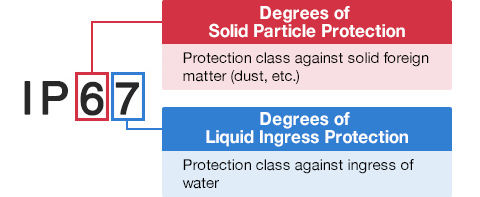
Ingress Protection (IP) ratings define the level of protection provided by enclosures to prevent the ingress of foreign objects (dust) and liquid into the electrical equipment.
International Standard IEC 60529 outlines an international classification system that describes the sealing characteristics of electrical equipment.
The classification system uses the “IP” code, or “Ingress Protection” code, to define the level of seal.
An IP number contains two numbers (i.e. IP67) in most instances which relate to the level of protection provided by an enclosure or housing.
Either number may be shown as “X” (i.e. IPX6 / IP7X) to indicate the “X” part is not tested.


Degrees of Solid Particle Protection – 1st Digit
| IP6x | No ingress of dust; complete protection against contact. (Dust tight) |
|---|---|
| IP5x | Protected from the amount of dust that would interfere with normal operation. (Dust protected) |
Degrees of Liquid Ingress Protection – 2nd Digit
| IPx8 | Protected against continuous immersion in water. Depth and duration specified by model. |
|---|---|
| IPx7 | Protected against temporary immersion in water for 1 m (3.3 ft) for 30 minutes |
| IPx6 | Protected against water projected by powerful jets from any direction. 100 L per minute by a powerful jets (12.5 mm) for 3 minutes. |
| IPx5 | Protected against water projected by jets from any direction. 12.5 L per minute by a nozzle (6.3 mm) for 3 minutes. |
| IPx4 | Protected against water splashed against the equipment from any direction |


