



Compact, Stylish and Packed with Features:
Color TFT LCD and NMEA 2000™ Connectivity
The IC-M430 is a stylish and compact VHF marine transceiver designed for modern vessels. Featuring a slimmer body with a sleek new flush mount method, it blends seamlessly into any helm layout. The color TFT LCD with a wide viewing angle and three display modes — Light, Dark, and Night — ensures clear visibility in any condition. With NMEA 2000™ and NMEA 0183-HS connectivity, the IC-M430 integrates effortlessly into your onboard network.
25 W RF Output with Class D DSC
For safety on the water, the IC-M430 offers 25 watts of transmit power. It provides built-in Class D DSC functionality for the distress calling button and direct calling.
Slimmer Body Fits in Tight Spaces
The compact 202 x 82 x 52.6 mm (8.0 x 3.2 x 2.1 inch) body provides exceptional installation flexibility. The slim depth profile enables installation in limited spaces while maintaining ample clearance behind the radio for proper cable management.


Simplified Flush Mounting
The radio features MFD-style mounting for elegant installation. Screw the radio directly into place, and snap-on body covers hide all mounting hardware for a clean finish. This mounting method is ideal for side pod installations on center console hard tops.
Three Display Modes for Comfortable Operation
First* color display in class. The wide viewing angle and bright screen deliver exceptional readability in any environment. Choose from Light mode, Dark mode, or Night mode, whether operating in direct sunlight or complete darkness, the display remains clearly visible. Seamlessly switch between Day and Night modes with a one-touch button. Backlit operation keys ensure confident operation in the dark.
According to lcom research as of September 2026.

Light mode

Dark mode

Night mode

Flexible System Integration
The radio offers plug-and-play installation via the NMEA 2000™, and also supports NMEA 0183-HS network, enabling data sharing between the radio and other marine electronics. Compatible with Icom MA-510TR, and you can transmit an Individual DSC call to a selected AIS target.

Installation example (HM-205RB + OPC-2522L + OPC-1000)
Remote Microphone Installation Options
The included hand microphone can be mounted directly to the front panel or rear-mounted using the extension cable OPC-1000*. For dual-station capability, the CommandMic™* provides full remote control from a second location (cable extension up to 60 ft/18.3 m) and supports intercom functionality between stations. Ideal for sailboat installations requiring a second control position at the helm. A 90° L-type adapter* is a useful addition that helps prevent connector damage.
Optional accessory
Built-in GNSS (GPS) Antenna
The IC-M430 features a built-in GNSS receiver with an internal antenna. For installations where satellite reception is limited, such as when mounted inside a cabin or enclosed area, an optional external GNSS antenna UX-241 is available.
Other Features
- VSWR (Voltage Standing Wave Ratio) detection function notifies antenna issues
- 25 W loud audio, hailer and foghorn functions
- Active noise canceling reduces background noise
- Dualwatch and Tri-watch function for monitoring Ch. 16 and/or call channel
- Optional flush mount kit for conventional installations
- IPX7 waterproof protection
- AquaQuake™ water draining function
- Weather channels with alert function
- Priority and normal scan
- Supports 4-digit channels
Related Product

CONNECTIONS

General
| Frequency range | TX | 156.025 ~ 157.425 MHz | |
|---|---|---|---|
| RX | 156.050 ~ 163.275 MHz | ||
| DSC | 156.525 MHz | ||
| Type of emission | 16K0G3E (FM), 16K0G2B (DSC) | ||
| Usable channels | USA, CAN, INT, WX channels | ||
| Power supply requirement | 13.8 V DC (11.7 ~ 15.9 V DC) | ||
| Current drain (at 13.8 V DC) |
TX 25 W output | 5.0 A maximum | |
| RX maximum audio |
Less than 1.6 A Less than 2.0 A (with HM-195) Less than 4.0 A (with ext SP) Less than 7.0 A (with ext SP, RX hailer, and HM-195) |
||
| Operating temperature range | –20°C ~ +60°C, –4°F ~ +140°F | ||
| Antenna impedance | 50 Ω | ||
| Audio power output (hailer) | 25 W typical | ||
| Dimensions (W x H x D) | 202 x 82 x 52.6 mm, 8.0 x 3.2 x 2.1 in | ||
| Weight (approximately) | 640 g, 1.4 lb (not including microphone) | ||
Transmitter
| Output power (at 13.8 V DC) | 25 W, 1W | |
|---|---|---|
| Max. frequency deviation | ±5 kHz | |
| Frequency tolerance | Less than ±0.5 kHz | |
| Spurious emissions | Less than −70 dBc (at 25 W) | |
| Adjacent channel power | More than 70 dB | |
| Residual modulation | More than 40 dB | |
Receiver
| Sensitivity (at 12 dB SINAD) DSC (1% BER) |
–13 dBμ typical –5 dBμ emf typical |
|
|---|---|---|
| Adjacent channel selectivity DSC (1% BER) |
More than 70 dB More than 73 dBμ emf |
|
| Spurious response DSC (1% BER) |
More than 70 dB More than 73 dBμ emf |
|
| Intermodulation DSC (1% BER) |
More than 70 dB More than 68 dBμ emf |
|
| Hum and noise | More than 40 dB | |
| Audio output power (at 10% distortion with 4 Ω) |
More than 10 W (external speaker) 16 W typical (RX hailer) |
|
Measurements made in accordance with TIA/EIA 603.
All stated specifications are subject to change without notice or obligation.
Applicable IP Rating
| Ingress Protection Standard | |
|---|---|
| Dust & Water | IPX7 (Waterproof protection) |
Supplied Accessories

DC/AF/DATA connector cable
- Speaker microphone, HM-205RB
- Microphone hanger
- DC/AF/DATA connector cable
- Mounting bracket kit
- Flush mount gasket, MBA-18
Dimensions


EXTERNAL SPEAKERS

MOUNTING BRACKETS


FLUSH MOUNT KITS

GPS ANTENNAS




Catalogs / Brochures
| Brochures Name | Size |
|---|---|
| IC-M430 | 2.36MB |
Instruction Manual / Guides
| Name | Model Name | Note |
|---|---|---|
| ABOUT THE MMSI CODE | IC-M430/IC-M430E | |
| Instruction Manual | IC-M430/IC-M430E | |
| CONNECTION GUIDE | IC-M430/IC-M430E |
Promotion Video
 CloseClose
Ingress Protection (IP) Code
Ingress Protection (IP) ratings define the level of protection provided by enclosures to prevent the ingress of foreign objects (dust) and liquid into the electrical equipment.
International Standard IEC 60529 outlines an international classification system that describes the sealing characteristics of electrical equipment.
The classification system uses the “IP” code, or “Ingress Protection” code, to define the level of seal.
An IP number contains two numbers (i.e. IP67) in most instances which relate to the level of protection provided by an enclosure or housing.
Either number may be shown as “X” (i.e. IPX6 / IP7X) to indicate the “X” part is not tested.

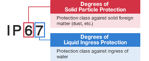
Degrees of Solid Particle Protection – 1st Digit
| IP6x | No ingress of dust; complete protection against contact. (Dust tight) |
|---|---|
| IP5x | Protected from the amount of dust that would interfere with normal operation. (Dust protected) |
Degrees of Liquid Ingress Protection – 2nd Digit
| IPx8 | Protected against continuous immersion in water. Depth and duration specified by model. |
|---|---|
| IPx7 | Protected against temporary immersion in water for 1 m (3.3 ft) for 30 minutes |
| IPx6 | Protected against water projected by powerful jets from any direction. 100 L per minute by a powerful jets (12.5 mm) for 3 minutes. |
| IPx5 | Protected against water projected by jets from any direction. 12.5 L per minute by a nozzle (6.3 mm) for 3 minutes. |
| IPx4 | Protected against water splashed against the equipment from any direction |