110 W 100% Duty Cycle Operation
Employing a high performance power amplifier, together with the solid heatsink built into the chassis, the IC-FR9010 series provides a reliable 100% duty cycle operation at 110W* output.
* 110W for VHF, 100W for UHF.
P25 Conventional, Analog FM and Mixed Mode
The IC-FR9010 series is compatible with both analog FM mode and P25 digital mode. Program digital and/or analog FM modes per channel. The mixed mode operation allows you to receive both analog FM and P25 digital modes and to transmit either mode depending on the received signal.
500 Memory Channels Capacity
The 4×20-characters display, 16 key buttons, 500 memory channels and internal speaker allow you to use the repeater as a simple base station or to check repeater activity. The bar graph display shows the S-meter level and output power level.
P25 Conventional Base Mode
As a P25 conventional base mode, the following P25 functions are programmable. (Conventional base mode only)
- Emergency
- Call alert
- Radio check
- Radio inhibit (Stun)
- Radio uninhibit (Revive)
- Status update
- Status request
- SBC log (Call log)
D-SUB 25-pin Accessory Connector
The IC-FR9010 series has a programmable D-SUB 25-pin accessory connector for connecting external remote control devices. Also, modulation/demodulation signals can be input/output from the D-SUB connector.
Programmable CTCSS, DTCS and NAC
The IC-FR9010 series decodes analog CTCSS and DTCS and digital NAC (Network Access Code) on a per channel basis and downlinks these with the received signal when required.
Other Features
- CW ID transmission
- High reliability, rugged construction
- ±1.5ppm frequency stability (Digital mode)
- Low standby current (280mA)
- P25 self-test mode and key test mode
- Automatic error detection
- 5 color LEDs
- 2U low profi le for rack mount
All other trademarks are the properties of their respective holders.
General
| IC-FR9010 | IC-FR9020 | |||
|---|---|---|---|---|
| Frequency coverage (Varies according to version) |
146–174MHz |
440–475MHz |
||
| Number of channels |
Max. 500 channels |
|||
| Channel spacing (Varies according to version) |
12.5/20/25/30kHz* |
|||
| Type of emission |
16K0F3E*, 11K0F3E, 8K10F1E/F1D |
|||
| Power supply requirement |
13.6V DC nominal |
|||
| Current drain (at 13.6V DC) |
Tx | High |
16A |
18A |
| Rx | Stand-by |
280mA |
||
| Max. audio |
3A |
|||
| Dimensions (projections not included; W×H×D) |
482×88×413 mm ; |
|||
| Weight (approx.) |
11.0kg ; 24.3lb |
|||
Transmitter
| IC-FR9010 | IC-FR9020 | ||
|---|---|---|---|
| RF output power (100% duty cycle) |
High |
110W |
100W |
| Low |
50W |
50W |
|
| Spurious emissions |
80dB min. |
76dB min. |
|
| Max. frequency deviation |
±5.0kHz/±2.5kHz (W/N) |
||
| Audio harmonic distortion |
3% typ. (60% deviation) |
||
| FM hum and noise |
55/50dB min. (W/N) |
||
Receiver
| IC-FR9010 | IC-FR9020 | ||
|---|---|---|---|
| Sensitivity | at 12dB SINAD |
0.30μV typ. |
|
| at 5% BER |
0.30μV typ. |
||
| Adjacent channel selectivity |
82/76dB min. (W/N) |
80/72dB min. (W/N) |
|
| Spurious response rejection |
95dB min. (W/N) |
85dB min. (W/N) |
|
| Intermodulation rejection |
79dB min. (W/N) |
77dB min. (W/N) |
|
| AF output power (at 5% distortion) |
7.5W typ. with 8Ω load |
||
* 25kHz bandwidth is no longer available for FCC Part 90 licensees for USA versions.
Ask your dealer if you need 25kHz bandwidth.
Applicable U.S. Military Specifications
Icom makes rugged products that have been tested to and passed the following MIL-STD requirements and strict environmental standards.
| Standard |
MIL-810 G | |
|---|---|---|
| Method | Procedure | |
| High Temperature Storage |
501.5 |
I |
| High Temperature Operation |
501.5 |
II |
| Low Temperature Storage |
502.5 |
I |
| Low Temperature Operation |
502.5 |
II |
| Vibration |
514.6 |
I |
| Shock Functional |
516.6 |
I |
Also meets equivalent MIL-STD-810-C, -D, -E and -F.
All stated specifications are subject to change without notice or obligation.
Catalogs / Brochures
| Brochures Name | Size |
|---|---|
| IC-FR9010/IC-FR9020 | 428KB |
| Business Radio Solutions (USA Edition) | 7.52MB |
Instruction Manual / Guides
| Name | Model Name | Note |
|---|---|---|
| Instruction Manual | IC-FR9010/IC-FR9020 |
Ingress Protection (IP) Code
Ingress Protection (IP) ratings define the level of protection provided by enclosures to prevent the ingress of foreign objects (dust) and liquid into the electrical equipment.
International Standard IEC 60529 outlines an international classification system that describes the sealing characteristics of electrical equipment.
The classification system uses the “IP” code, or “Ingress Protection” code, to define the level of seal.
An IP number contains two numbers (i.e. IP67) in most instances which relate to the level of protection provided by an enclosure or housing.
Either number may be shown as “X” (i.e. IPX6 / IP7X) to indicate the “X” part is not tested.

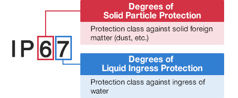
Degrees of Solid Particle Protection – 1st Digit
| IP6x | No ingress of dust; complete protection against contact. (Dust tight) |
|---|---|
| IP5x | Protected from the amount of dust that would interfere with normal operation. (Dust protected) |
Degrees of Liquid Ingress Protection – 2nd Digit
| IPx8 | Protected against continuous immersion in water. Depth and duration specified by model. |
|---|---|
| IPx7 | Protected against temporary immersion in water for 1 m (3.3 ft) for 30 minutes |
| IPx6 | Protected against water projected by powerful jets from any direction. 100 L per minute by a powerful jets (12.5 mm) for 3 minutes. |
| IPx5 | Protected against water projected by jets from any direction. 12.5 L per minute by a nozzle (6.3 mm) for 3 minutes. |
| IPx4 | Protected against water splashed against the equipment from any direction |