High Visibility OLED Screen

Operating information is clearly shown on the OLED display.
The OLED (Organic Light Emitting Diode) emits light from itself, so a display backlight is not required. It provides higher contrast, wider viewing angle of almost 180 degrees and faster response time than a conventional LCD. The IC-A220's display has a wide active area, allowing operating frequencies to be maximized in the display, while operating status can be shown on both top and bottom of the display.
Large Switch Buttons
The IC-A220 has large switch buttons on the front panel. The most frequently used FLIP-FLOP (Frequency exchange) switch button is designed large enough to be pushed with ease. All switch buttons and knobs are illuminated with pure-white backlighting, which are the same color as the OLED display.
Auto Squelch Function
The squelch sensitivity is automatically adjusted in accordance with the noise level to eliminate annoying background noise and unwanted signals.
Quick Squelch Adjustment
The auto and manual squelch including squelch level can be quickly adjusted with the Volume knob. The squelch test function temporarily opens the squelch and allows you to monitor signals
GPS Memory Function
When connected to an external GPS receiver* equipped with an airport frequency database, the frequency data such as nearby airports can be transferred and made available in the IC-A220.
* Ask your dealer for available GPS receiver details.
Optional Power Supply PS-80 for the Ground
When combined with the IC-A220, the optional PS-80 power supply provides a convenient base station operation on the ground. The PS-80 includes built-in speaker and HM-176 hand microphone.
Auto Dimmer
The auto dimmer function sets display and key backlighting brightness. The ICA220’s high sensitivity light sensor covers a wide illumination range.
External Dimmer Control
By connecting to an external dimmer control system on the aircraft, the ICA220’s dimmer function can be linked with the aircraft dimmer level.
Intercom Function
The IC-A220 has a built-in voice activated intercom function allowing the pilot to talk with the copilot via the headset. The IC-A220 has adjustable audio level and squelch control functions.
Remote Control Capability
You can remotely control the FLIP-FLOP (frequency exchange), intercom and recall switches via the rear panel connector
8.33 kHz Channel Spacing
The IC-A220 allows switching between 8.33 kHz and 25 kHz frequency steps in the menu mode.
* Use of 8.33 kHz channel spacing may be prohibited depending on country.
Memory Channels
The IC-A220 has 20 memory channels and 20 history memory channels respectively. Often used memory channels can be instantly recalled. Group memory channels are organized into 10 memory channels by five groups (total 50 channels). Weather channel scanning function searches for weather channel signals.
Other Features
- Dualwatch and priority watch functions
- One touch access to 121.5 MHz emergency frequency
- Side tone function for monitoring your voice with a headset
- ANL (Automatic noise limiter) function reduces pulse type noise
- Remote control capability
- PC programming capability
- Dial lock and panel lock
- Time-out-timer
- D-SUB 25-pin connector and MIL-Spec M39029/63-368 compliant socket pins
- Slim 33 mm (1.3 inch) height can be installed in a limited panel space
- Two types of menu mode; settings menu and configuration menu
- Both 13.8 V and 27.5 V electrical systems compatible
Rear Panel View

General
| Frequency range | TX/RX | 8.33 kHz spacing | 118.000–136.992 MHz |
|---|---|---|---|
| 25 kHz spacing | 118.000–136.975 MHz | ||
| RX | Weather channel | 161.650–163.275 MHz | |
| Frequency spacing | 8.33 kHz / 25 kHz | ||
| Mode | AM (6K00A3E, 5K60A3E) | ||
| Frequency stability | ±5 ppm | ||
| Operating temperature | –20˚C to +55˚C; –4˚F to +131˚F | ||
| Antenna impedance | 50 Ω | ||
| Number of memory channels | 20 regular, 50 group memory, 10 GPS, 20 history, 10 weather | ||
| Power supply requirement | 13.8 V/27.5 V DC (Negative ground) | ||
| Dimensions (W × H × D, Projections not included) |
160 × 34 × 271 mm; 6.3 × 1.34 × 10.67 in |
||
| Weight (approximately) | 1.0 kg; 2.2 lb | ||
Transmitter
| Output power | 8 W (Carrier power) | |
|---|---|---|
| Spurious emission | –60 dBc | |
| Modulation limiting | 70% (Maximum 98%) | |
| Microphone impedance | 600Ω | |
Receiver
| Intermediate frequencies | 38.85 MHz/450 kHz (1st/2nd) | |
|---|---|---|
| Sensitivity | AM (6 dB S/N) | Less than 2μV |
| FM (12 dB SINAD) | Less than 1.4μV | |
| Selectivity | 25 kHz spacing | ±3 kHz/±22 kHz (6 dB/60 dB) |
| 8.33 kHz spacing | ±2.778 kHz/±7.37 kHz (6 dB/60 dB) | |
| Spurious response | More than 74 dBμ | |
| Audio output power | External SP | 5 W with a 4 Ω load |
| Headphone | 60 mW with a 500 Ω load | |
Applicable U.S. Military Specifications
| Standard |
MIL-810 G | |
|---|---|---|
| Method | Procedure | |
| Low Temperature | 502.5 | I,II |
| Temperature Shock | 503.5 | I-C |
| Solar Radiation | 505.5 | I |
| Humidity | 507.5 | II |
| Vibration | 514.6 | I |
| Shock | 516.6 | I |
Also meets equivalent MIL-STD-810-C, -D -E and -F.
Supplied Accessories
- Mounting bracket kit
Measurements made in accordance with RTCA DO-186B.
All stated specifications are and subject to change without notice or obligation.
MICROPHONES

EXTERNAL SPEAKERS

POWER SUPPLY

MOUNTING BRACKETS

ADAPTERS

Catalogs / Brochures
| Brochures Name | Size |
|---|---|
| IC-A220 | 231KB |
| Aviation Radios | 2.31MB |
| Aviation Radios (European Edition) | 1.81MB |
Instruction Manual / Guides
| Name | Model Name | Note |
|---|---|---|
| Instruction Manual | IC-A220 (Non-TSO) | |
| Installation Guide | IC-A220 (Non-TSO) |
Ingress Protection (IP) Code
Ingress Protection (IP) ratings define the level of protection provided by enclosures to prevent the ingress of foreign objects (dust) and liquid into the electrical equipment.
International Standard IEC 60529 outlines an international classification system that describes the sealing characteristics of electrical equipment.
The classification system uses the “IP” code, or “Ingress Protection” code, to define the level of seal.
An IP number contains two numbers (i.e. IP67) in most instances which relate to the level of protection provided by an enclosure or housing.
Either number may be shown as “X” (i.e. IPX6 / IP7X) to indicate the “X” part is not tested.
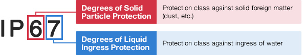
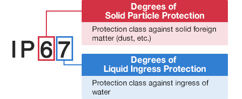
Degrees of Solid Particle Protection – 1st Digit
| IP6x | No ingress of dust; complete protection against contact. (Dust tight) |
|---|---|
| IP5x | Protected from the amount of dust that would interfere with normal operation. (Dust protected) |
Degrees of Liquid Ingress Protection – 2nd Digit
| IPx8 | Protected against continuous immersion in water. Depth and duration specified by model. |
|---|---|
| IPx7 | Protected against temporary immersion in water for 1 m (3.3 ft) for 30 minutes |
| IPx6 | Protected against water projected by powerful jets from any direction. 100 L per minute by a powerful jets (12.5 mm) for 3 minutes. |
| IPx5 | Protected against water projected by jets from any direction. 12.5 L per minute by a nozzle (6.3 mm) for 3 minutes. |
| IPx4 | Protected against water splashed against the equipment from any direction |