Large, Bright OLED Display
The IC-A210 has an organic light emitting diode (OLED) display. The display offers many advantages in brightness, vividness, contrast, viewing angle and response time compared to a conventional display. In addition, the auto dimmer function adjusts the display for optimum brightness at day or night.
Easy Channel Selection
It's fast and easy to select any of the memory channels in the IC-A210. The "flip-flop" arrow button switches between main and stand-by channels. The dualwatch function allows you to monitor two channels simultaneously. In addition, the auto stack memory stores the last 10 channels used and allows you to recall those channels easily.
GPS Memory Function
When connected to an external GPS receiver* equipped with an airport frequency database, the frequency data such as nearby airports can be transferred and made available in the IC-A210.
* Ask your dealer for available GPS receiver details.
12 V/24 V DC Power Source
The built-in DC-DC converter accepts a 12/24 V DC power source. The IC-A210 is easily installed in most airplanes or vehicles.
Intercom Functions
The IC-A210 has a built-in voice activated intercom function allowing the pilot to talk with the co-pilot via the headset. The IC-A210 has adjustable audio level and squelch control functions.
Easy Installation
The IC-A210 neatly fits inside the common mounting brackets used on most airplanes including Icom's IC-A200. Two types of rear-panel adapters are included, allowing for streamlined plug-in connectivity.
* Ask your dealer for compatible panel mount radio details.
Other Features
- 8.33 kHz/25 kHz channel spacing (Depending on version)
- NOAA weather channel receive (USA version only)
- One touch access to 121.5 MHz emergency frequency
- Side tone function
- ANL (Automatic noise limiter) function
- Remote control capability
- Time-out-timer
- PC programmable
General
| Frequency range | TX/RX | 8.33 kHz spacing 118.000–136.992 MHz 25 kHz spacing 118.000–136.975 MHz |
|
|---|---|---|---|
| RX WX Channels | 161.650–163.275 MHz (USA only) | ||
| Number of memory channels | 240 ch (Max.) | ||
| Channel spacing | 8.33 kHz / 25 kHz | ||
| Power supply requirements | 13.8/27.5 V DC (automatic selection) |
||
| Current drain | TX | 5.0 A Max. | |
| RX | Stand-by | 500 mA | |
| Max. audio | 4.0 A | ||
| Dimensions (W×H×D) (Projections are not included) |
160×34×271 mm 6.3×1.34×10.67 in |
||
| Weight | 1.0 kg; 2.2 lb | ||
| Operating temperature range | –20°C to +55°C | ||
| Frequency stability | ±5 ppm | ||
Transmitter
| RF output power | 8.0 W typ. (Carrier power) | |
|---|---|---|
| Microphone impedance | 600 Ω | |
Receiver
| Sensitivity | 2 μV (6dB S/N) | |
|---|---|---|
| Selectivity | 6 dB: ±3 kHz / ±2.778 kHz 60 dB: ±22 kHz / ±7.37 kHz (25 kHz / 8.33 kHz spacing) |
|
| Spurious response rejection | 74 dBμ | |
| Audio output power (at 10% distortion) |
5 W typ. with a 4 Ω load 60 mW with a 500 Ω load |
|
Applicable U.S. Military Specifications
The IC-A210 has been tested to and passed the following MIL-STD requirements and strict environmental standards.
| Standard | MIL-810 F Method, Proc. |
|---|---|
| Low Pressure Storage | 500.4 I |
| Low Pressure Operation | 500.4 II |
| High Temperature Storage | 501.4 I |
| High Temperature Operation | 501.4 II |
| Low Temperature Storage | 502.4 I |
| Low Temperature Operation | 502.4 II |
| Temperature Shock | 503.4 I |
| Solar Radiation | 505.4 I |
| Humidity | 507.4 |
| Vibration | 514.5 I |
| Shock Functional | 516.5 I |
Also meets equivalent MIL-STD-810-C, -D and -E.
All stated specifications are subject to change without notice or obligation.
Supplied Accessories
- Mounting bracket kit
- Rear panel adapter, MB-113*
* Depending on version
Catalogs / Brochures
| Brochures Name | Size |
|---|---|
| Aviation Radios | 2.31MB |
| IC-A210 | 257KB |
| Aviation Radios (European Edition) | 1.81MB |
Instruction Manual / Guides
| Name | Model Name | Note |
|---|---|---|
| Instruction Manual | IC-A210 | |
| INSTALLATION GUIDE | IC-A210/IC-A210E |
Ingress Protection (IP) Code
Ingress Protection (IP) ratings define the level of protection provided by enclosures to prevent the ingress of foreign objects (dust) and liquid into the electrical equipment.
International Standard IEC 60529 outlines an international classification system that describes the sealing characteristics of electrical equipment.
The classification system uses the “IP” code, or “Ingress Protection” code, to define the level of seal.
An IP number contains two numbers (i.e. IP67) in most instances which relate to the level of protection provided by an enclosure or housing.
Either number may be shown as “X” (i.e. IPX6 / IP7X) to indicate the “X” part is not tested.

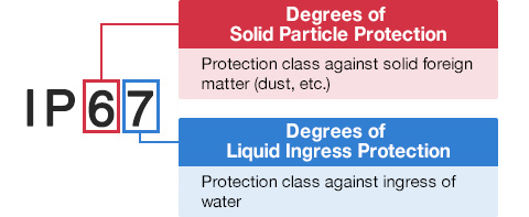
Degrees of Solid Particle Protection – 1st Digit
| IP6x | No ingress of dust; complete protection against contact. (Dust tight) |
|---|---|
| IP5x | Protected from the amount of dust that would interfere with normal operation. (Dust protected) |
Degrees of Liquid Ingress Protection – 2nd Digit
| IPx8 | Protected against continuous immersion in water. Depth and duration specified by model. |
|---|---|
| IPx7 | Protected against temporary immersion in water for 1 m (3.3 ft) for 30 minutes |
| IPx6 | Protected against water projected by powerful jets from any direction. 100 L per minute by a powerful jets (12.5 mm) for 3 minutes. |
| IPx5 | Protected against water projected by jets from any direction. 12.5 L per minute by a nozzle (6.3 mm) for 3 minutes. |
| IPx4 | Protected against water splashed against the equipment from any direction |