5 Watt RF Output Power
5 Watts (High) and 1 Watt (Low) selectable output power.

Seven-Colour Backlight LCD
The colour of the LCD Screen can be changed to reflect the operating status. Different colours can be assigned to channels, and colours can be set to indicate when scanning or transmitting.

Noise Reduction, Audio Equalizer & Voice Changer
The Noise Reduction reduces background noise from both transmit and receive audio.

Voice Recorder & Instant Play Back
Can record up to 10 messages of 30 seconds each, for a total of 5 minutes.

Supports Both 12 V/24 V DC Power Sources
Accepts a 12/24 V DC power source and it is suitable for most types of cars and trucks.

Dynamic Group Scan for Keeping Group Communication
Using a CTCSS or DTCS tone, this function finds an open channel for group communicaton.

Loud Speaker-Microphone with Auto Volume Control
The microphone monitors ambient noise levels and automatically adjusts the audio level.

IP54 Water Resistance & Dust Protection
General
| IC-455 | |||
|---|---|---|---|
| Frequency coverage | CB | 476.425–477.4125 MHz | |
| RX | 400.000–520.000 MHz (RX only) | ||
| Mode | 8K50F3E | ||
| Number of channels | Max 256 channels/8 banks | ||
| Antenna impedance | 50 Ω | ||
| Input impedance (MIC) | 600 Ω | ||
| Output impedance (Audio) | 4 Ω | ||
| Intermediate frequency | 1st 49.95 MHz, 2nd 450 kHz | ||
| Operating temperature range | - 10℃ to +60℃ | ||
| Power supply voltage | 13.8 or 27.6 V DC nominal (Negative ground) |
||
| Current drain with HM-244 | 27.6 V DC | RX stand-by | 300 mA (approx.) |
| RX Maximum audio | 1000 mA (approx.) | ||
| TX (5 W output) | 1500 mA (approx.) | ||
| 13.8 V DC | RX stand-by | 500 mA | |
| RX Maximum audio | 1500 mA | ||
| TX (5 W output) | 3000 mA | ||
| Dimensions (projections not included) |
Main unit | 125 (W) × 29 (H) × 160 (D) mm | |
| HM-244 | 62.1 (W) × 101.5 (H) × 30.5 (D) mm | ||
| Weight (approx.) | Main unit | 344 g | |
| Main unit with HM-244 | 535 g | ||
Transmitter
| IC-455 | |
|---|---|
| Output power | 5W / 1W (selectable) |
| Modulation system | Variable reactance frequency modulation |
| Max. frequency deviation | ±2.5 kHz |
| Frequency stability | ±2.5 ppm |
| Spurious emissions | –30 dBm max. (5 W: 67 dBc) |
| Adjacent channel power | –16 dBm max. (5 W: 53 dBc) |
| Audio harmonic distortion | 1% typical (60% deviation) |
| Residual modulation | 40 dB typical |
| Limiting characteristic of modulator | 70 to 100% of maximum deviation |
Receiver
[CB (476.425–477.4125 MHz)]
| IC-455 | |
|---|---|
| Sensitivity (12 dB SINAD): | 0.22 μV typical |
| Squelch sensitivity | 0.2 μV typical (Threshold) |
| Hum and noise | 48 dB typical |
| Intermodulation rejection ratio | 72 dB typical |
| Spurious response rejection ratio | 80 dB typical |
| Adjacent channel selectivity | 68 dB typical |
| Conducted spurious radiation | –57 dBm max. (9 kHz–1.0 GHz) –47 dBm max. (1.0 GHz–4.0 GHz) |
| Audio output power | 5.0 W max. at 10% distortion with 4 Ω load |
| Audio frequency response | +2 dB to −8 dB of 6 dB/octave from 300 Hz to 2550 Hz |
[RX (400.000–520.000 MHz)] (Except CB (476.425–477.4125 MHz))
| IC-455 | |
|---|---|
| Sensitivity (12 dB SINAD) | 0.25 μV typical |
| Hum and noise: | 45 dB typical |
| Conducted spurious radiation | –57 dBm max. (9 kHz–1.0 GHz) –47 dBm max. (1.0 GHz–4.0 GHz) |
| Audio frequency response | +2 dB to –8 dB of 6 dB/octave from 300 Hz to 2550 Hz |
Measurements made in accordance with AS/NZS 4365-2011 (R2016), AS/NZS 4295:2015.
All stated specifications are subject to change without notice or obligation.
Supplied Accessories
- Speaker-microphone, HM-244
- DC power cable
- Mounting bracket for Main unit
- Microphone hanger
EXTERNAL SPEAKERS

SOFTWARE

PROGRAMMING/DATA CABLES
EXTENSION CABLES

Catalogs / Brochures
| Brochures Name | Size |
|---|---|
| IC-455 | 1.47MB |
Instruction Manual / Guides
| Name | Model Name | Note |
|---|---|---|
| INSTRUCTION MANUAL | IC-455 |
Ingress Protection (IP) Code
Ingress Protection (IP) ratings define the level of protection provided by enclosures to prevent the ingress of foreign objects (dust) and liquid into the electrical equipment.
International Standard IEC 60529 outlines an international classification system that describes the sealing characteristics of electrical equipment.
The classification system uses the “IP” code, or “Ingress Protection” code, to define the level of seal.
An IP number contains two numbers (i.e. IP67) in most instances which relate to the level of protection provided by an enclosure or housing.
Either number may be shown as “X” (i.e. IPX6 / IP7X) to indicate the “X” part is not tested.
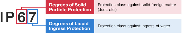
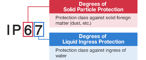
Degrees of Solid Particle Protection – 1st Digit
| IP6x | No ingress of dust; complete protection against contact. (Dust tight) |
|---|---|
| IP5x | Protected from the amount of dust that would interfere with normal operation. (Dust protected) |
Degrees of Liquid Ingress Protection – 2nd Digit
| IPx8 | Protected against continuous immersion in water. Depth and duration specified by model. |
|---|---|
| IPx7 | Protected against temporary immersion in water for 1 m (3.3 ft) for 30 minutes |
| IPx6 | Protected against water projected by powerful jets from any direction. 100 L per minute by a powerful jets (12.5 mm) for 3 minutes. |
| IPx5 | Protected against water projected by jets from any direction. 12.5 L per minute by a nozzle (6.3 mm) for 3 minutes. |
| IPx4 | Protected against water splashed against the equipment from any direction |