High Power and Full Duty Cycle Operation

LDMOS Transistor <MRFX1K80HR5>
The IC-PW2 uses new 65 V LDMOS power transistors, MRFX1K80HR5 and a high-efficiency power supply. 1 kW output and 1-hour continuous transmission can be achieved with 200 V AC input (at ambient temperature 25 ℃.) It can be operated at full power operation after booting up the IC-PW2. Of course, you can operate it continuously, even in long contest hours, or FT8 operation.


Increased Linearity & Clean Transmission with the Digital Pre-Distortion (DPD) Technology (with the IC-7610)
The IC-PW2 has succeeded in realizing the world's first*1 DPD as a linear amplifier for amateur radio in combination with the IC-7610. This technology corrects the signal distortion from the IC-PW2, by applying inverse distortion to the output signal from the IC-7610 exciter in advance*2.
*1 According to our research as of July 2023.
*2 Not applied in non-linear modulation such as FM, FSK, and MSK modes.


2 × 6 Automatic Antenna Selector

Two radio inputs and six antenna connectors provide fully automatic antenna switching capabilities. Each antenna can be selected independently when making a band change on either transceiver. You can operate it as if you had two linear amplifiers. When using dual independent receivers, which the IC-7610 and IC-7851 have, you can watch dual bands at once by using two antennas.
Powerful SO2R Features
Single Operator Two Radios (SO2R) operation is possible with one IC-PW2. While you are making a call on one radio*1, you can watch another band on the other radio. The transmitter lockout function*2 prevents simultaneous transmission of two radios during SO2R operation.


*1 Performance may deteriorate depending on the performance/specifications of the BPF and exciter, antenna installation conditions, and other factors. In such cases, please take measures such as using two sets of BPFs.
*2 Compatible Radio linked operation is available with IC-7851, IC-7610, and IC-7300 (firmware upgrade required.)
SO2R Operation Possible with Just One Multi-band BPF

Conventional linear amplifiers require two multi-band BPFs to prevent suppression of receive sensitivity by their own transmit signal when operating SO2R. However, the IC-PW2 automatically connects the multi-band BPF to the receiving radio when you select either radio to transmit. This makes SO2R operation possible with just one Multi-band BPF*.
* Performance may deteriorate depending on the performance/specifications of the BPF and exciter, antenna installation conditions, and other factors. In such cases, please take measures such as using two sets of BPFs.
RX-ANT Connectors for Multi-band BPF and External Equipment
User supplied bandpass filters (BPF), preamps, and attenuators can be connected to the [RX-ANT] connectors. When you use two radios with the IC-PW2, one multi-band BPF can be shared with these radios by switching the receiving radio. In addition, the band switching of multi-band BPF can be controlled from the band signal output connector. The [BAND 1], [BAND 2] signal output connectors, can each be set to either [INPUT 1], [INPUT 2], transmitter side, or receiver side. It can be linked with band switching of various external devices.
Completely Linked with Icom Radio Operation*
With compatible Icom radios, various settings are easy, and you can get the full performance out of the IC-PW2. When you operate the transceiver by changing bands and frequency tuning, the IC-PW2 automatically works in conjunction with it. It provides an extremely quick response in contests and multi-band operations.
* Compatible Radio linked operation is available with IC-7851, IC-7610, and IC-7300 (firmware upgrade required.)
Built-in Automatic Antenna Tuner

By using mechanical relays, the antenna tuner can quickly retune the operating band in two to three seconds. The IC-PW2 has also succeeded in reducing unnecessary emissions during tuning. The antenna tuner works even when the power amplifier function is not used.
Detachable Controller with Touch Screen Color Display

A remote-control cable (3 m, 9.8 ft) enables the amplifier to be mounted away from the radios for a big station installation. The 4.3 inch color display is a touch screen with a graphical user interface. Connected antennas are graphically shown on the display.
Advanced Remote Control with the RS-PW2

The optional RS-PW2 enables remote control of all IC-PW2 functions, including Power ON/OFF, from your Windows™ PC. When used together with the RS-BA1 or the IC-7760 remote controller (RC-7760), it supports advanced operation from your remote shack.
Other Features
- High-efficiency and low noise cooling system
- Various error detection circuits protect internal components
- An SD card slot on the front panel for firmware updates and saving settings
- Remote AUX jack for controlling an automatic tuning telescopic antenna
- Antenna quick select function that can connect to priority antenna with simple action
- LAN connector for Internet/LAN remote control
Rear Panel View


Specifications
| Frequency coverage | 1.9, 3.5, 7, 10, 14, 18, 21, 24, 28, 50 MHz bands (Amateur bands) | |
|---|---|---|
| Output power | 1 kW (180 ~ 264 V AC), 500 W (90 ~ 132 V AC) | |
| Driving power | Maximum 100 W | |
| Power supply requirements | 90 ~ 132 V AC or 180 ~ 264 V AC | |
| Power consumption | 2000 VA (100 V AC) 3000 VA (200 V AC) |
|
| Spurious emissions | -60/-70 dB or less (HF/50 MHz band) | |
| Antenna connector | Input | PL–239 × 2 (50 Ω) |
| Output | PL–239 × 6 (50 Ω) | |
| Tuner matching range | 16.7 ~ 150.0 Ω (HF ~ 50 MHz) | |
| Tuning accuracy | VSWR 1: 1.5 or less | |
| Tuning time | Average | 2 ~ 3 seconds |
| Maximum | 15 seconds | |
| Usable temperature range | -10 ℃ ~ +40 ℃, +14 ℉ ~ +104 ℉ | |
| Dimensions (W×H×D) | 425 × 149 × 445 mm, 16.7 × 5.9 × 17.9 in (Projections not included) | |
| Weight (Approximate) | 22 kg, 48.5 lb | |
All stated specifications are subject to change without notice or obligation.
Supplied Accessories
- ACC cable (3 m, 9.8 ft)
- Control cable (3 m, 9.8 ft)
- Coaxial cable (3 m, 9.8 ft)
- Mini plug cable (3 m, 9.8 ft)
- Bracket for controller
- Front plate (for separated RF unit)
Dimensions


Optional Accessories
ADAPTER CABLES

CABLES


SOFTWARE

Some options may not be available in some countries. Please ask your dealer for details.
All Mode


Digital Pre-Distortion (DPD)
-

- OPC-2501
- DPD FEEDBACK CABLE
-

- IC-PW2
- HF/50 MHz 1 kW LINEAR AMPLIFIER
POWER AMPLIFIER
-
- IC-PW2
- HF/50 MHz 1 kW LINEAR AMPLIFIER
-

- OPC-599
- ADAPTER CABLE
POWER AMPLIFIER
-
 Discontinued product
- IC-PW1
- 1 kW LINEAR AMPLIFIER
-
- IC-PW2
- HF/50 MHz 1 kW LINEAR AMPLIFIER
-
- OPC-599
- ADAPTER CABLE
Catalogs / Brochures
| Brochures Name | Size |
|---|---|
| HAM Radios and Receivers | 3.28MB |
| HAM Radios and Receivers (European Edition) | 3.49MB |
| IC-PW2 (A4) | 1.20MB |
| IC-PW2 (LT) | 1.18MB |
| RS-PW2 | 2.07MB |
Instruction Manual / Guides
| Name | Model Name | Note |
|---|---|---|
| INSTRUCTION MANUAL | IC-PW2 | |
| BASIC MANUAL (Spanish/French) | IC-PW2 | |
| CI-V REFERENCE GUIDE | IC-PW2 | |
| Firmware Update Information | IC-PW2 | |
| DICHIARAZIONE DI CONFORMITA UE (ITALIANO) | IC-PW2 | |
| DOC (DECLARATION OF CONFORMITY) | IC-PW2 | |
| BASIC MANUAL (German/Italian) | IC-PW2 |
Firmware / Software
| Type | Model Name | Version | Last Update |
|---|---|---|---|
| Firmware | IC-PW2 | Version 1.31 | 2025.08.13 |
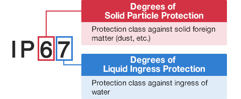
Ingress Protection (IP) Code
Ingress Protection (IP) ratings define the level of protection provided by enclosures to prevent the ingress of foreign objects (dust) and liquid into the electrical equipment.
International Standard IEC 60529 outlines an international classification system that describes the sealing characteristics of electrical equipment.
The classification system uses the “IP” code, or “Ingress Protection” code, to define the level of seal.
An IP number contains two numbers (i.e. IP67) in most instances which relate to the level of protection provided by an enclosure or housing.
Either number may be shown as “X” (i.e. IPX6 / IP7X) to indicate the “X” part is not tested.

Degrees of Solid Particle Protection – 1st Digit
| IP6x | No ingress of dust; complete protection against contact. (Dust tight) |
|---|---|
| IP5x | Protected from the amount of dust that would interfere with normal operation. (Dust protected) |
Degrees of Liquid Ingress Protection – 2nd Digit
| IPx8 | Protected against continuous immersion in water. Depth and duration specified by model. |
|---|---|
| IPx7 | Protected against temporary immersion in water for 1 m (3.3 ft) for 30 minutes |
| IPx6 | Protected against water projected by powerful jets from any direction. 100 L per minute by a powerful jets (12.5 mm) for 3 minutes. |
| IPx5 | Protected against water projected by jets from any direction. 12.5 L per minute by a nozzle (6.3 mm) for 3 minutes. |
| IPx4 | Protected against water splashed against the equipment from any direction |