



Clear to See, Simple to Use, Dual‑band Mobile Transceiver that Expands Your Operating Possibilities with a Full Range of Advanced Features.
The ID-5200E is a new digital transceiver covering the VHF/UHF bands. It features a large touchscreen display and, combined with a waterfall display that shows band conditions at a glance, delivers outstanding visibility and intuitive operation.
The ID‑5200E offers a comprehensive set of D‑STAR features, including Terminal Mode, Access Point Mode, and DV repeater monitoring. A future firmware update will also add support for APRS. The ID‑5200E is additionally equipped with Wi‑Fi® and Bluetooth® connectivity. By connecting to the Internet via Wi‑Fi, Terminal Mode and Access Point Mode can be operated even more conveniently. It can also connect wirelessly to smartphones, allowing comfortable use of applications and more. In addition, it supports full dual-watch reception including DV/DV, enabling efficient operation.

Touch operation image※
A Large Touchscreen Color Display with Excellent High Visibility
The ID-5200E features the same large 4.3-inch color display used in the IC-705 and IC-7300MK2. The touchscreen interface allows quick and intuitive access to settings such as frequency, mode, and other key functions. Furthermore, it is equipped with an automatic dimming function that adjusts the LCD backlight to the optimal brightness according to ambient light levels, as well as a key backlight that makes key operation easier at night or in dark environments. Visibility is greatly improved, allowing you to check a wide range of information more quickly.
The in-vehicle installation example uses the Mount Base MBF-1 〈optional〉 and Controller Bracket MBA-20 〈optional〉.

Independent dual-band dials
Independent Dual-band Dials for Superior Operability
The main dial, along with the volume and squelch controls, is arranged in a symmetrical layout for smooth and intuitive operation, including tuning and other frequently used functions. In addition, commonly accessed menus, functions, and quick settings are assigned to physical keys, ensuring fast and effortless operation.

Touch assist image
Touch Assist feature that supports in-vehicle operations
When the main dial is pushed, the Touch Assist screen appears. Frequently used items such as Band, Mode, and TS (Tuning Step) are displayed in large format, enabling more reliable selection and configuration.
Waterfall Display for At-a-Glance Band Conditions
The ID-5200E is the first mobile transceiver to incorporate both a band scope and a waterfall display. The band scope provides detailed information on signal activity, band conditions, and available frequencies. The waterfall display further enhances visibility by allowing you to review received signal history over time and easily identify weak signals. Display modes include Center mode, FIX mode, and FIX Scroll mode, giving you flexible options to suit your operating style.
Center Mode

Displays received signals within a fixed range centered on the current receiving frequency.
FIX Mode

Displays received signals within a fixed range centered on the receiving frequency set in "FIX Mode Center Frequency."
Scroll FIX Mode

Displays received signals within a fixed range centered on the receiving frequency set in "FIX Mode Center Frequency." If the reception marker moves beyond the display range, the view scrolls to follow it.

Memory scope image
Memory Scope Function
The memory scope function displays the reception status of 31 channels (the selected channel ±15) or 41 channels (±20) simultaneously in Memory mode or DR mode. In addition to the scope view, a waterfall display is also supported.*
The memory scope operates in Center mode only.
Enhanced D‑STAR Functionality, Including Terminal Mode and Access Point Mode
Terminal Mode and Access Point Mode
Even from locations where you cannot access a repeater, you can connect to the internet via Wi-Fi® to communicate over D-STAR. You can enjoy D-STAR without being affected by the availability or location of the nearest repeater. In addition, even in environments where a global IP address is not assigned, standby operation in Terminal Mode/Access Point Mode is possible*. These features enable easier and more flexible D-STAR operation.
Reception of all calls is not guaranteed. In environments where a global IP address is assigned and port forwarding is available, please set UDP Hole Punch to OFF.


DV repeater monitor image
DV Repeater Monitor Function
The DV Repeater Monitor lets you check activity on the destination repeater during Area CQ via D-STAR. By accessing the repeater used to broadcast the area CQ via the Internet and actively monitoring the situation, you can determine when an ongoing communication has ended. Monitoring works with domestic and overseas repeaters, and reception from the nearest repeater always takes priority so you will never miss calls to your own station.

Transmission and reception image
Image Transmission and Reception
The ID-5200E allows you to send, receive, and view stored images using only the main unit. Photos taken with a smartphone can be transferred to the ID-5200E via built-in Wi-Fi® or Bluetooth® connectivity.

Wi-Fi® connection image
Connectivity for Smartphone and PC with Wi-Fi®/Bluetooth® Function
The ID-5200E supports connectivity via Wi‑Fi® (compatible with 2.4GHz/5GHz bands) and Bluetooth® functions. Using the Wi‑Fi feature to access the Internet enables smoother operation in both Terminal Mode and Access Point Mode. It can also connect wirelessly to a smartphone, making it highly convenient when using control software, image‑trimming applications, and similar tools. Control software, image trimming utility software, and other applications can also be used by connecting to a smartphone via Wi-Fi® / Bluetooth® functions. The ID-5200 also supports the online update function* which automatically updates the latest D-STAR repeater lists and firmware via Wi-Fi®.
* To use the online update function, the radio must be connected to the Internet and have a microSD card inserted.
Supports APRS®* (Automatic Packet Reporting System)

APRS® image
The ID-5200E will support APRS®*, a communication protocol that utilizes packet radio to transmit and receive real-time information such as location data, messages, and weather reports. The built-in KISS mode TNC has been implemented since the first production run, enabling APRS operation from a PC.
Planned for support in a future firmware update
Dualwatch including DV/DV
The receiver section features independent and identical receiving circuits for both MAIN and SUB. It supports full dualwatch including not only FM/FM and FM/DV, but also DV/DV. It is possible to operate with FM/DV (Terminal Mode) and listen to audio from 2 frequencies/modes simultaneously. This enables operations such as receiving from 2 D-STAR repeaters simultaneously, or monitoring another repeater while engaged in communication.

DV/DV mode image 1

DV/DV mode image 2

FM/FM mode image

Dualwatch in Terminal mode image
Supports a wide range of reception, including VHF/UHF airband and FM radio
In addition to VHF, the radio supports Airband reception in the UHF range (225 ~ 400 MHz). Simultaneous dual-band reception of V/V, U/U, and V/U combinations is also available in the Airband. You can enjoy not only communication, but also a wide variety of reception.

V/V airband mode image

V/U airband mode image
Built with an advanced high‑precision GPS (GNSS) receiver
Equipped with a GPS (GNSS) receiver compatible with "Michibiki," enabling sub-meter high-precision positioning. It displays highly accurate own-station position information and transmits location data, delivering strong performance in APRS® and D-PRS. It also offers features such as automatic position response, GPS logging, and automatic listing of nearby repeaters.
The positioning accuracy of latitude/longitude/altitude may vary depending on signal reception conditions.

Own position information image

Nearest repeater information image
Flexible Mounting Options in the Vehicle
Using optional accessories such as the MBA-20 controller bracket and the MBF-1 mount base, the unit can be securely installed in a vehicle. A wide range of additional mounting options is also available, including the MBF‑11 bracket for docking the main unit and the MBA‑19 bracket for desktop placement. Furthermore, the device supports AMPS-pattern mounting holes and standard 1/4-inch camera tripod screws, allowing flexible installation methods to suit various in-vehicle environments.

MBA-19

MBF-11
Compatible with the Optional HM‑209 Noise‑cancelling Microphone (optional accessory)
Using DSP technology, the unit automatically reduces noise and wind interference, delivering natural and clear audio that is easy to hear.
Extensive Memory Capabilities
- Equipped with 1,000 memory channels, 100 skip channels, 4 call channels (2 × 2 bands), 2,500 repeater list channels, 300 calling list channels, 300 GPS memory channels, and 50 sets of program scan edges. Ample memory capacity is provided even for heavy users.
Other Features
- USB Type-C™ connectivity is available for use with PCs and smartphones.
- Built‑in microSD card slot for storing transmission/reception logs and voice recordings.
- Convenient memory management functions, including direct CSV data import.
- Speech function for frequency, receive mode, and call sign announcements.
Front/Rear view of the main unit

Front view of the main unit

Rear view of the main unit

Rear view of the controller
General
| Frequency coverage |
Transmit FM/FM-N/DV : 144.000~148.000 MHz, 430.000~440.000 MHz
FM/FM-N/DV : 137.000~174.000 MHz, 225.000~550.000 MHz* * 225.000~399.995 MHz is supported by only FM/FM-N. |
|
|---|---|---|
| Type of emission | F1D, F2D, F3E, F7W | |
| Mode | FM, FM-N, DV, AM, AM-N | |
| Operating temperature range | −10°C to +60°C | |
| Frequency stability | ±2.5 ppm | |
| Antenna impedance | 50 Ω | |
| Number of memory channels |
1000 memory channels, 100 skip channels, 4 call channels (2 x 2 bands), 2500 repeater list channels, 300 callsign list channels, 300 GPS memory channels, and 50 sets of programming scan edge |
|
| Power supply requirements |
DC 13.8 V ±15% |
|
| Current drain | RX Stand-by | 1.2 A |
| Max. audio | 1.8 A (Dualwatch reception, External speaker 8 Ω, max. AF output) | |
| TX | 13.0 A | |
| Dimensions (W×H×D, projections not included) |
Main unit |
150.0 x 40.0 x 171.5 mm |
| Controller |
163.0 x 8.35 x 24.1 mm |
|
| Weight (approx.) | Main unit | 1.28 kg |
| Controller | 0.26 kg | |
Transmitter
| Output power | 50 W, 15 W, 5 W | |
|---|---|---|
| Modulation system | FM, FM-N | FM reactance modulation |
| DV | GMSK reactance modulation | |
| Max. frequency deviation |
Less than ±5.0 kHz (FM), Less than ±2.5 kHz (FM-N) |
|
| Spurious emissions | Less than −60 dBc | |
| Microphone impedance | 600 Ω | |
Receiver
| Intermediate frequencies | A band | 1st IF : 58.05 MHz/2nd IF : 450 kHz |
|---|---|---|
| B band | 1st IF : 57.15 MHz/2nd IF : 450 kHz | |
| Sensitivity | FM/FM-N (12 dB SINAD) | Less than -15 dBμ |
| DV (1% BER) | Less than -15 dBμ | |
| Receiver sensitivity |
FM/FM-N (12 dB SINAD) |
137.000 ~ 143.995 MHz Less than -10 dBμ 144.000 ~ 159.995 MHz Less than -10 dBμ 160.000 ~ 174.000 MHz Less than 0 dBμ 225.000 ~ 249.995 MHz Less than 0 dBμ 250.000 ~ 299.995 MHz Less than -10 dBμ 300.000 ~ 374.995 MHz Less than 0 dBμ 375.000 ~ 399.995 MHz Less than 0 dBμ 400.000 ~ 499.995 MHz Less than -10 dBμ 500.000 ~ 550.000 MHz Less than -5 dBμ |
| AM (10 dB S/N) |
118.000 ~ 136.995 MHz Less than 0 dBμ 137.000 ~ 143.995 MHz Less than 0 dBμ 225.000 ~ 249.995 MHz Less than 10 dBμ 250.000 ~ 299.995 MHz Less than 0 dBμ 300.000 ~ 374.995 MHz Less than 10 dBμ 375.000 ~ 399.995 MHz Less than 10 dBμ |
|
| Squelch sensitivity | Less than -18 dBμ (Threshold) | |
| Selectivity | FM | More than 60 dB |
| FM-N | More than 55 dB | |
| DV | More than 50 dB | |
| Spurious and image rejections | More than 60 dB (VHF/UHF) |
|
| Audio output power | More than 2.0 W (with 8Ω load, 10% distortion) |
|
| External speaker connector | 8 Ω | |
All stated specifications are subject to change without notice or obligation.
Supplied accessories
- Hand microphone, HM-232
- DC power cable
- Controller cable (3.5 m; 11.5 ft)
MICROPHONES


EXTERNAL SPEAKERS


MOUNTING BRACKETS


SOFTWARE



PROGRAMMING/DATA CABLES


EXTENSION CABLES


ADAPTER CABLES


News
Catalogs / Brochures
| Brochures Name | Size |
|---|---|
| HAM Radios and Receivers (European Edition) | 2.99MB |
| OPTION LIST - HAM Radios and Receivers (European Edition) | 5.44MB |
| ID-5200E | 2.61MB |
Instruction Manual / Guides
| Name | Model Name | Note |
|---|---|---|
| INSTRUCTIONS | CS-5200 | |
| About the Share Pictures function | IC-9700/IC-705/IC-905/ID-5200A/ID-5200E | |
| D-STAR D-PRS Guide (Basic/Advanced) | ID-31A/ID-31E/ID-31A PLUS/ID-31E PLUS/ID-51A/ID-51E/ID-51A PLUS/ID-51E PLUS/ID-51A PLUS2/ID-51E PLUS2/IC-7100/ID-50A/ID-50E/ID-52A/ID-52E/ID-52A PLUS/ID-52E PLUS/IC-705/IC-905/ID-4100A/ID-4100E/ID-5100A/ID-5100E/ID-5200A/ID-5200E/IC-9700 | |
| Firmware Update Information | ID-5200A/ID-5200E | |
| ADVANCED MANUAL (English) | ID-5200A/ID-5200E | |
| CONNECTION GUIDE | ID-5200A/ID-5200E | |
| BASIC MANUAL (Spanish/French) | ID-5200A/ID-5200E | |
| BASIC MANUAL (English) | ID-5200A/ID-5200E | |
| CI-V REFERENCE GUIDE | ID-5200A/ID-5200E | |
| About the DV Gateway function (For Mobiles) | ID-5200A/ID-5200E | |
| D-STAR Using the GPS Logger function | ID-5200A/ID-5200E/ID-52A PLUS/ID-52E PLUS/ID-52A/ID-52E/IC-705/ID-51A/ID-51E/ID-31A/ID-31E/ID-31A PLUS/ID-31E PLUS/ID-50A/ID-50E | |
| BASIC MANUAL (German/Italian) | ID-5200E | |
| DICHIARAZIONE DI CONFORMITA UE (ITALIANO) | ID-5200E | |
| DOC (DECLARATION OF CONFORMITY) | ID-5200E | |
| D-STAR Application Guide | ID-52A PLUS/ID-52E PLUS/ID-52A/ID-52E/IC-705/IC-905/IC-9700/IC-7100/ID-4100E/ID-4100A/ID-5100E/ID-5100A/ID-51E/ID-51A/ID-31E/ID-31A/ID-31E PLUS/ID-31A PLUS/RS-MS1A/RS-MS1I/RS-MS3A/ST-4001A/ST-4001I/ID-50A/ID-50E/ID-5200A/ID-5200E | |
| D-STAR Updating the repeater list | ID-52A PLUS/ID-52E PLUS/ID-52E/ID-52A/IC-705/IC-905/IC-9700/IC-7100/ID-4100E/ID-4100A/ID-5100E/ID-5100A/ID-51E/ID-51A/ID-31E/ID-31A/ID-31E PLUS/ID-31A PLUS/ID-50A/ID-50E/ID-5200A/ID-5200E | |
| INSTRUCTIONS | ST-4001A/ST-4001I | |
| INSTRUCTIONS | ST-4001W | |
| INSTRUCTIONS | ST-4002A | |
| Installation Guide for Windows 11 | USB Driver IC-705/IC-905/IC-R15/ID-52A/ID-52E/ID-50A/ID-50E/ID-52A PLUS/ID-52E PLUS/IC-7760/IC-7300MK2/ID-5200A/ID-5200E |
Firmware / Software
| Type | Model Name | Version | Last Update |
|---|---|---|---|
| Programming software | CS-5200 | Version 1.10 | 2026.09.18 |
| USB Driver | IC-705/IC-905/IC-R15/ID-52A/ID-52E/ID-50A/ID-50E/ID-52A PLUS/ID-52E PLUS/IC-7760/IC-7300MK2/ID-5200A/ID-5200E | Version 1.80 | 2026.08.26 |
| Firmware | ID-5200A, ID-5200E | Version 1.10 | 2026.09.18 |
Promotion Video
 CloseClose
Ingress Protection (IP) Code
Ingress Protection (IP) ratings define the level of protection provided by enclosures to prevent the ingress of foreign objects (dust) and liquid into the electrical equipment.
International Standard IEC 60529 outlines an international classification system that describes the sealing characteristics of electrical equipment.
The classification system uses the “IP” code, or “Ingress Protection” code, to define the level of seal.
An IP number contains two numbers (i.e. IP67) in most instances which relate to the level of protection provided by an enclosure or housing.
Either number may be shown as “X” (i.e. IPX6 / IP7X) to indicate the “X” part is not tested.

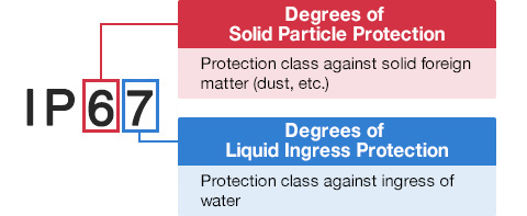
Degrees of Solid Particle Protection – 1st Digit
| IP6x | No ingress of dust; complete protection against contact. (Dust tight) |
|---|---|
| IP5x | Protected from the amount of dust that would interfere with normal operation. (Dust protected) |
Degrees of Liquid Ingress Protection – 2nd Digit
| IPx8 | Protected against continuous immersion in water. Depth and duration specified by model. |
|---|---|
| IPx7 | Protected against temporary immersion in water for 1 m (3.3 ft) for 30 minutes |
| IPx6 | Protected against water projected by powerful jets from any direction. 100 L per minute by a powerful jets (12.5 mm) for 3 minutes. |
| IPx5 | Protected against water projected by jets from any direction. 12.5 L per minute by a nozzle (6.3 mm) for 3 minutes. |
| IPx4 | Protected against water splashed against the equipment from any direction |