Alphanumeric Readout
Seven characters can be programmed into each memory channel to conveniently display
station names or ship names for simplified operation.
150 W Output Power
A large cooling fan system, in combination with the aluminum chassis, allows conditions for transmission at a full 150 W* (PEP) RF output power—even during demanding RTTY (radio teletype) operation.
*60 W (PEP) above 24 MHz bands.
Other Features
・ General coverage receiver
・ Terminals for frequency/mode control via NMEA interfacing
・ Automatic tuning function
・ Large, front-mounted speaker
・ Weather fax ready
・ Backlight control
・ CW full break-in and semi break-in
・ 2-tone alarm built-in (Optional depending on version)
・ 1136 channels available
| Frequency range | TX | 1.6–2.9999 MHz 4.0–4.9999 MHz 6.0–6.9999 MHz 8.0–8.9999 MHz 12.0–13.9999 MHz 16.0–17.9999 MHz 18.0–19.9999 MHz 22.0–22.9999 MHz 25.0–27.5000 MHz |
|---|---|---|
| RX | 0.5–29.9999 MHz | |
| Power supply requirement | 13.6 V DC ±15% (negative ground) | |
| Dimensions (W×H×D) (Projections not included) |
291.4×116.4×315 mm; 11.47×4.58×12.4 in |
|
| Weight (approx.) | 7.8 kg; 17.2 lb | |
| Current drain (approx.) | Transmit (High) | 30 A at max. power |
| Max. audio output | 2.5 A | |
| Sensitivity (1.8–29.999 MHz) |
J3E,J2B,R3E,A1A (12 dB SINAD) | 0.5 μV |
| H3E (10 dB S/N) | 3.2 μV | |
| Spurious response rejection (1.6-29.999 MHz) | More than 70 dB | |
| Audio output power (10% dist/ 4 Ω load) | 4 W | |
| RF output power (PEP) (output power differs depending on version) |
150/60/20 W (below 24 MHz) 60/20 W (above 24 MHz) |
|
All stated specifications are subject to change without notice or obligation.
Supplied Accessories
- Hand microphone
- DC power cable
- ACC plugs
- Mounting bracket kit
- Microphone hanger
- Speaker plug
- Spare fuses
MICROPHONES

ANTENNAS


INTERNAL UNITS

Catalogs / Brochures
| Brochures Name | Size |
|---|---|
| IC-M710 | 183KB |
| Marine Radios | 7.14MB |
Instruction Manual / Guides
| Name | Model Name | Note |
|---|---|---|
| Instruction Manual | IC-M710 |
Ingress Protection (IP) Code
Ingress Protection (IP) ratings define the level of protection provided by enclosures to prevent the ingress of foreign objects (dust) and liquid into the electrical equipment.
International Standard IEC 60529 outlines an international classification system that describes the sealing characteristics of electrical equipment.
The classification system uses the “IP” code, or “Ingress Protection” code, to define the level of seal.
An IP number contains two numbers (i.e. IP67) in most instances which relate to the level of protection provided by an enclosure or housing.
Either number may be shown as “X” (i.e. IPX6 / IP7X) to indicate the “X” part is not tested.
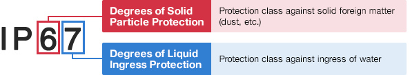
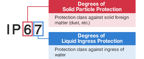
Degrees of Solid Particle Protection – 1st Digit
| IP6x | No ingress of dust; complete protection against contact. (Dust tight) |
|---|---|
| IP5x | Protected from the amount of dust that would interfere with normal operation. (Dust protected) |
Degrees of Liquid Ingress Protection – 2nd Digit
| IPx8 | Protected against continuous immersion in water. Depth and duration specified by model. |
|---|---|
| IPx7 | Protected against temporary immersion in water for 1 m (3.3 ft) for 30 minutes |
| IPx6 | Protected against water projected by powerful jets from any direction. 100 L per minute by a powerful jets (12.5 mm) for 3 minutes. |
| IPx5 | Protected against water projected by jets from any direction. 12.5 L per minute by a nozzle (6.3 mm) for 3 minutes. |
| IPx4 | Protected against water splashed against the equipment from any direction |