ACTIVE SATELLITE ANTENNA SYSTEM FOR THE IC-SAT100
AH-41
Active Satellite Antenna System for Using the IC-SAT100 Satellite PTT Radio in a Building

Descriptions
・Covers both Iridium® satellite frequencies and GNSS L1 band frequencies, and provides a solution for satellite communications indoors
・Use optional OPC-2462 (59 m, 193.5 ft) or user supplied coaxial cable (Max. 169 m, 554.5 ft) to obtain a line-of-sight path to the satellite
・Power over Coaxial (PoC) carries electrical power through the coaxial cable
– Electrical power cabling can be reduced
・Separate TX/RX unit configuration, TX unit with a Power Amplifier and RX unit with a LNA (Low Noise Amplifier)
・The main unit has IP67 waterproof and dust-tight protection for outdoor installation
Connection example

Types of External Antennas for IC-SAT100 and Usage Guidelines

By replacing the IC-SAT100 antenna with an external antenna, satellite communication is possible even from a vehicle or building. Select the most suitable antenna according to the installation location and application.
1 OPC-2422 coaxial cable (5 m, 16.4 ft) is required for more than 1.5 m, 4.9 ft extension.
2 Optional OPC-2113 or user supplied coaxial cable is separately required. Cable loss requirement is less than 3.4 dB loss at 1621 MHz.
3 Optional OPC-2462 or user supplied coaxial cable is separately required. Cable loss requirement is 12.5 - 13.0 dB loss at 1621 MHz.
4 The distance from the main unit to the antenna is a rough guideline. The height of the building is an estimate assuming that the height of one floor is 3.5 m, 11.5 ft .
Specifications
GENERAL
| Frequency range | 1616.02–1626.48 MHz (TX unit/RX unit) 1575.42–1605.4 MHz (RX unit, GNSS L1 band) |
|---|---|
| Antenna impedance | 50 Ω nominal (N-J connector) |
| Polarization | Right-hand circular |
| Operating temperature range | –25°C to +55°C, –13°F to +131°F |
| Current drain (approximate) |
Less than 2.5 A (at relay) Less than 0.8 A (stand-by) |
| Dimensions (W × H × D) (projections not included) |
310 × 326 × 89 mm (TX/RX units + bracket) 77 × 200 × 77 mm (each unit) |
| Weight (approximate) | 1.6 kg, 3.5 lb |
TX UNIT
| Rated output power | 37.7 dBm ± 1 dB (at 23.3 dBm input to TX unit) |
|---|---|
| Spurious emissions | 0.25 μW (≤ 1 GHz), 1.0 μW (> 1 GHz) |
RX UNIT
| Total gain | 17 dB ±1.5 dB (at –80 dBm input to RX unit) |
|---|---|
| Noise figure | Less than 3.0 dB |
| Spurious emissions | 0.25 μW (≤ 1 GHz), 1.0 μW (> 1 GHz) |
All stated specifications are subject to change without notice or obligation.
Applicable IP Rating
| Ingress Protection StandardData | |
|---|---|
| IP rating (AH-41 main unit) | IP67 (Waterproof and dust-tight) |
Packing Includes

OPC-2461
Coaxial cable (1.5 m, 4.9 ft)

BC-253
Power box

BC-228
AC adapter

Mounting kit
(U-bolts, pole clamps, washers and nuts)
Optional Accessory

OPC-2462
Coaxial cable (59 m, 193.5 ft)
Suggested Main Antenna Cables
Use optional OPC-2642 or user supplied coaxial cable to meet Iridium® performance requirements, and comply with FCC regulations.
| Cable loss requirement from Power box to the AH-41 | 12.5–13.0 dB loss at 1621 MHz |
|---|
| Reference Cable | Diameter | Cable Length |
|---|---|---|
| Times Microwave Systems | ||
| LMR 195 | 4.95 mm, 0.195 inch | 27 m, 88.6 ft |
| LMR 240 | 6.10 mm, 0.240 inch | 39 m, 128.0 ft |
| LMR 300 | 7.62 mm, 0.300 inch | 49 m, 160.8 ft |
| LMR 400 | 10.29 mm, 0.405 inch | 75 m, 246.1 ft |
| LMR 500 | 12.70 mm, 0.500 inch | 92 m, 301.8 ft |
| LMR 600 | 14.99 mm, 0.590 inch | 115 m, 377.3 ft |
| LMR 900 | 22.10 mm, 0.870 inch | 169 m, 554.5 ft |
Above cable lengths are for your reference which are calculated by the target cable loss at 1500 MHz.
Satellite PTT

EXTERNAL ANTENNA
-

- AH-41
- ACTIVE SATELLITE ANTENNA SYSTEM FOR THE IC-SAT100
-

- OPC-2462
- COAXIAL CABLE
Use optional OPC-2462 (59 m, 193.5 ft) or user supplied coaxial cable (Max. 169 m, 554.5 ft)
Catalogs / Brochures
| Brochures Name | Size |
|---|---|
| AH-41 | 957KB |
Instruction Manual / Guides
| Name | Model Name | Note |
|---|---|---|
| DICHIARAZIONE DI CONFORMITA UE (ITALIANO) | AH-41 | |
| DOC (DECLARATION OF CONFORMITY) | AH-41 | |
| INSTRUCTIONS | AH-41 |
Ingress Protection (IP) Code
Ingress Protection (IP) ratings define the level of protection provided by enclosures to prevent the ingress of foreign objects (dust) and liquid into the electrical equipment.
International Standard IEC 60529 outlines an international classification system that describes the sealing characteristics of electrical equipment.
The classification system uses the “IP” code, or “Ingress Protection” code, to define the level of seal.
An IP number contains two numbers (i.e. IP67) in most instances which relate to the level of protection provided by an enclosure or housing.
Either number may be shown as “X” (i.e. IPX6 / IP7X) to indicate the “X” part is not tested.
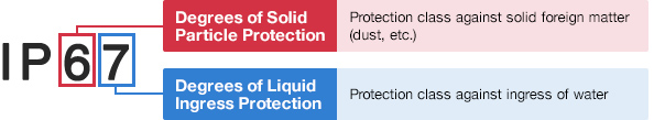
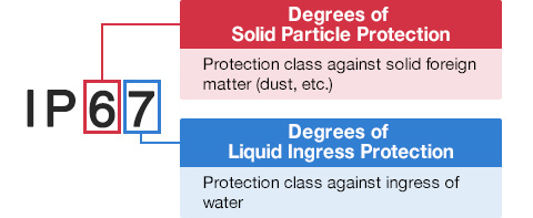
Degrees of Solid Particle Protection – 1st Digit
| IP6x | No ingress of dust; complete protection against contact. (Dust tight) |
|---|---|
| IP5x | Protected from the amount of dust that would interfere with normal operation. (Dust protected) |
Degrees of Liquid Ingress Protection – 2nd Digit
| IPx8 | Protected against continuous immersion in water. Depth and duration specified by model. |
|---|---|
| IPx7 | Protected against temporary immersion in water for 1 m (3.3 ft) for 30 minutes |
| IPx6 | Protected against water projected by powerful jets from any direction. 100 L per minute by a powerful jets (12.5 mm) for 3 minutes. |
| IPx5 | Protected against water projected by jets from any direction. 12.5 L per minute by a nozzle (6.3 mm) for 3 minutes. |
| IPx4 | Protected against water splashed against the equipment from any direction |