MARINE RADAR
MR-1220
Series
12.1-inch Color Radar with Simplified ARPA & 3D View

- 2 ft, 4 kW Radome Scanner MR-1220R4
- 4 ft, 4 kW Open Array Scanner MR-1220T4
- 4 ft, 6 kW Open Array Scanner MR-1220T6
- 6 ft, 6 kW Open Array Scanner MR-1220T6L
Simplified Automatic Radar Plotting Aids (ARPA) Function
The simplified ARPA function*1 *2 assists you to prevent your vessel from colliding with other vessels or objects. When a target enters the preset watch area, it is automatically tracked on the radar echo. By selecting one of the targets, the target information, such as position, course, speed, CPA (Closest Point of Approach), TCPA (Time to CPA), bearing, and distance is displayed. When a target enters the CPA, or it exceeds the set TCPA, an alarm sounds to warn you.

Simplified ARPA
Digital Selective Calling (DSC) Information Display function
When connected to a DSC radio and a DSC call is received, the received message is displayed on the MR-1220*1. The function shows the DSC message, and the location where the DSC call is transmitted. Up to 20 DSC messages can be plotted. A Man Overboard waypoint can also be displayed.

Received DSC example
Automatic Identification System (AIS) Overlay Function

Compatible Icom marine DSC
radio example,IC-M605
When connected to an external AIS device (including Icom IC-M605 and IC-M506 AIS), up to 100 AIS target icons are overlaid on the radar echo*1. By selecting an AIS icon, vessel information such as AIS class, MMSI number, vessel name, course, speed, CPA, TCPA, bearing, and distance is displayed.

AIS Overlay function

Other v AIS Overlay function essel AIS information
External Buzzer Connection

On the deck
The MR-1220 has an external buzzer terminal on the rear panel. You can sound an alarm beeper to effectively inform of danger, when a target enters the CPA or it exceeds the TCPA*3.
Plot Function

Plot function example
The Plot function*1 records your vessel's longitude and latitude at the set time interval, and displays your track on the radar echo.
3D Display Function
The MR-1220 provides an intuitive bird's-eye view. You can change the display angle according to your own preference. The 2D view can be displayed at the same time.

3D display (20°)

3D display (40°) with the 2D view
Multi-Lingual User Interface

Language setting display
You can select the display language from English, Indonesian, Korean, Malay, Rus s ian, Spanish, Thai, and Vietnamese.
Optional Video Output Unit*3

With the optional UX-234 video output unit, the MR-1220 can be connected to an external display. The same radar echoes can be displayed on the main and secondary displays at the same time.
Scanner Unit Selections

SC-R40
2 ft 4 kW Radome Scanner (MR-1220R4)

SC-T40
4 ft 4 kW Open Array Scanner (MR-1220T4)

SC-T60
4 ft 6 kW Open Array Scanner (MR-1220T6)

SC-T60L
6 ft 6 kW Open Array Scanner (MR-1220T6L)
Other Features
- Target Latitude Longitude (TLL) function*1
- True Trail function*1
- Two user programmable alarm zones
- Waypoint indication
- Power Save function ....and more
*1 External bearing, speed, position, waypoint, variation, AIS and DSC data is (are) required, when you use these functions.
*2 Up to 20 targets are automatically tracked. Additional 10 targets can be tracked when manually set (Automatic Tracking Aid function).
*3 User supplied.
*4 UX-234 optional video output unit required.
Display Unit
| DISPLAY UNIT | MR-1220R4 | MR-1220T4 | MR-1220T6 | MR-1220T6L |
|---|---|---|---|---|
| Display | 12.1-inch color TFT LCD | |||
| Resolution (H × V) | 600 × 800 dots | |||
| Minimum range | 25 m; 82 ft (at 1/8 NM range) | |||
| Maximum range | 36 NM | 48 NM | 72 NM | 72 NM |
| Power supply requirement | 12/24 V DC | |||
| Dimensions (W × H × D; projections not included) | 301 × 323.5 × 119.2 mm | |||
| Weight (approx.) | 4.8 kg | |||
| Usable temperature range | −15 °C to +55 °C | |||
| Power consumption (approx.) | 60 W | 70 W | 80 W | 90 W |
| Available scanner unit | 2 ft (60 cm) radome | 4 ft (120 cm) open array | 4 ft (120 cm) open array | 6.5 ft (200 cm) open array |
Scanner Unit
| SCANNER UNIT | SC-R40 (MR-1220R4) |
SC-T40 (MR-1220T4) |
SC-T60 (MR-1220T6) |
SC-T60L (MR-1220T6L) |
|
|---|---|---|---|---|---|
| Type | 2 ft (60cm) radome | 4 ft (120 cm) open array | 4 ft (120 cm) open array | 6.5 ft (200 cm) open array | |
| Peak output power | 4 kW | 4 kW | 6 kW | ||
| Rotation speed | 24, 36 rpm typical | 24, 36 rpm typical | 22, 24, 36 rpm typical | ||
| Beamwidth | Horizontal | 4° typical | 2° typical | 2° typical | 1.2° typical |
| Vertical | 22° typical | 23° typical | 23° typical | 23° typical | |
| Sidelobe | −22 dB typical | −24 dB typical | −24 dB typical | −27 dB typical | |
| Transmission frequency | 9410 MHz ±30 MHz | 9410 MHz ±30 MHz | 9410 MHz ±30 MHz | ||
| Dimensions (W × H × D; projections not included) | 640 × 256 × 640 mm | 1217 (dia.) × 395 (H) mm | 1217 (dia.) × 395 (H) mm | 1995 (dia.) ×395 (H) mm | |
| Weight (approx.) | 8 kg | 18 kg | 18 kg | 20 kg | |
| Usable temperature range | –25 °C to +70 °C | –25 °C to +70 °C | –25 °C to +70 °C | ||
| Connection cable | 15 m (OPC-2341) |
20 m (OPC-2342) |
20 m (OPC-2342) |
||
Applicable IP Rating
| Ingress Protection Standard | |
|---|---|
| Display unit | IPX4 (Water resistance) |
| Scanner unit | IPX6 (Powerful jet water protection) |
All stated specifications are subject to change without notice or obligation.
Supplied Accessories
- Scanner unit
- System cable


INTERNAL UNITS

Catalogs / Brochures
| Brochures Name | Size |
|---|---|
| MR-1220 Series | 1.56MB |
| Marine Radios | 7.14MB |
Instruction Manual / Guides
| Name | Model Name | Note |
|---|---|---|
| INSTRUCTION MANUAL | MR-1220/MR-1220R4 |
Marine Radars MR-1220 / MR-1010RII Introduction
Ingress Protection (IP) Code
Ingress Protection (IP) ratings define the level of protection provided by enclosures to prevent the ingress of foreign objects (dust) and liquid into the electrical equipment.
International Standard IEC 60529 outlines an international classification system that describes the sealing characteristics of electrical equipment.
The classification system uses the “IP” code, or “Ingress Protection” code, to define the level of seal.
An IP number contains two numbers (i.e. IP67) in most instances which relate to the level of protection provided by an enclosure or housing.
Either number may be shown as “X” (i.e. IPX6 / IP7X) to indicate the “X” part is not tested.
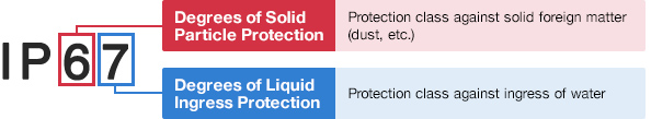
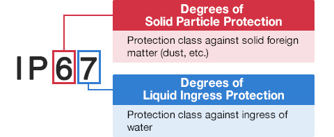
Degrees of Solid Particle Protection – 1st Digit
| IP6x | No ingress of dust; complete protection against contact. (Dust tight) |
|---|---|
| IP5x | Protected from the amount of dust that would interfere with normal operation. (Dust protected) |
Degrees of Liquid Ingress Protection – 2nd Digit
| IPx8 | Protected against continuous immersion in water. Depth and duration specified by model. |
|---|---|
| IPx7 | Protected against temporary immersion in water for 1 m (3.3 ft) for 30 minutes |
| IPx6 | Protected against water projected by powerful jets from any direction. 100 L per minute by a powerful jets (12.5 mm) for 3 minutes. |
| IPx5 | Protected against water projected by jets from any direction. 12.5 L per minute by a nozzle (6.3 mm) for 3 minutes. |
| IPx4 | Protected against water splashed against the equipment from any direction |